 Loading... Please wait...
Sign up for our newsletter
You can also follow us on twitter.
Our Newsletter
(older) Instructions and Software Download:
Note: These instructions only apply to the non-native MIDI verions (pre 0.20). This version was based on a USB HID protocol.
- MAX OS X Installer (10.3+ only).
- OS X User Manual
- Max/MSP Demo app | source - A demo app that lets you turn the VMeter into a simple instrument, a volume meter for your computer's mic, and a display of all 8 internal sensors.
- OS X Source Code (MIT license) - Contains code for changing system volume, accessing USB HID devices, sending MIDI messages and other useful stuff that you're free to repurpose however you like.
- Windows Installer (XP, Vista, Win 7) (source code and full instructions coming soon)
- Note: You'll also need "Virtual MIDI cables" to connect route MIDI to and from other software. We recommend CooperLan's music connection system, which has an additional benefit of being able to route over networks!
- Windows Manual
- Windows VC++ Source Code (coming soon)
- HID USB Protocol - Want to use the VMeter as a general purpose controller / display? This will guide you in interfacing with it on linux, windows or even a USB host shield for arduino.
- Older software releases - The original system volume control & display for mac & pc. No MIDI support in this version.
OS X Manual:
vmeter.net for more help, support@vmeter.net for direct support
Software Installation: Download the OS X software from VMeter.net/instructions and open the .dmg file. Drag it to the applications folder. Run the program by finding it in your applications folder and double clicking.
Getting Started: Run the software. There should be a V in the upper right of your screen in the status bar:

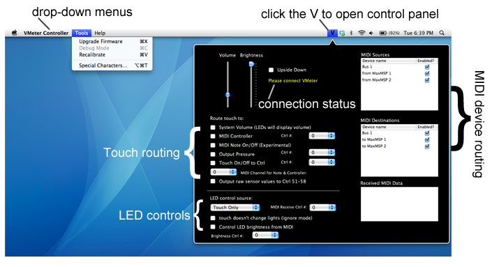
Plug in the VMeter to any USB port on your computer or powered USB hub (the hub must have its own power supply). The software automatically detects the VMeter, and should say which version of the hardware it found in yellow. If no VMeter is detected, it will say “Please connect VMeter” in yellow in the pop-up window.
Usage and Sensitivity: The VMeter works best when it’s stationary. In its current design, moving objects behind or to its side may be detected, so holding it in your hand may not work well all the time. It should work well in most situations, however, as it’s always adjusting to the surrounding environment. If you have any issues, shoot us an email at support@VMeter.net. You can also try unplugging and replugging, or selecting “Recalibrate” from the “Tools” drop-down menu.
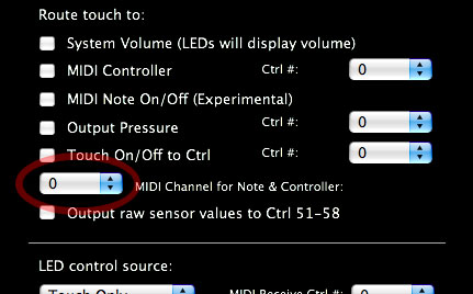
Routing Touch to MIDI Controller Messages: The VMeter can send out a variety of different MIDI messages, including:
- MIDI Controller: VMeter behaves like a standard fader, useful for track volumes or filter frequencies, etc.
- Touch On/Off: Sends 127 when touched, and 0 when not touched. Can be used to gate on/off sounds or effects
- Output Pressure: Sends out an approximation of pressure as a MIDI controller message. Note: in actuality, it’s measuring the total finger area on the touch surface, so two fingers will act the same as one finger pressed very hard.
- Raw Sensor Values: Sends out 8 controller messages (controller numbers 50-57) corresponding to the signal coming from all 8 of the internal capacitive sensors. This can be used to detect proximity as well as touch, although you still need to be fairly close. Values typically range from 15 to 127. Note that the reference values for this output are sampled when the VMeter or software is first started. If the behavior seems strange, try unplugging and replugging the USB cable at the computer side. You can also choose “Tools” and then “Recalibrate.”
- MIDI Note On/Off (experimental): This sends out a note-on message when the VMeter is touched, and a note-off message when released. The pitch goes from 60 to 62 depending on where the VMeter was touched. This feature is still in development, but if you like the idea and want more flexibility, let us know! (support@VMeter.net).
You can activate some or all of the different controller outputs at once, depending on your computer’s resources. Just select the appropriate checkbox, and then choose what controller number you want for the control. You’ll also want to select a MIDI Channel on which to broadcast.
Finally, if your software appears in the “MIDI Destinations” list, be sure to check the box. Some software will not appear there, but will work nonetheless (Ableton LIVE, for example).
Performance tip: by default, the VMeter creates and sends all of its messages on its own bus, labeled “Bus 1.” If you’re low on computer resources, deselect “Bus 1” in the “MIDI Sources” and “MIDI Destinations” lists.
Refer to your music software’s instruction for how to setup the mapping between the controller messages coming from the VMeter and the controls inside the software.
Routing MIDI Controller Messages to the LEDs: The VMeter can also accept controller messages that change the LEDs. For instance, with Max/MSP, you could sample the volume of some sound and send that out via a MIDI controller message to display on the VMeter as a sound level meter. You can also route a controller to the LED’s brightness.
Use the “LED Control Source” drop-down box to select “MIDI Controller” as the LED control source. Note: touches will still override the messages unless the “touch doesn’t change” box is checked.
Individual LED control: Although only columns can currently be drawn, the ability to control every individual LED is already supported in the VMeter’s firmware, and can be accessed by a little re-writing of the software. This requires some programming knowledge. The source code is available on the instructions page at VMeter.net.
Brightness: Use the “Brightness” slider to adjust the brightness of the LEDs from all the way off to max brightness (16). As mentioned in the previous section, you can also have the brightness respond to MIDI controller messages (0-127 is scaled to 0-16).
Controlling System Volume: Check the “System Volume” box to control the computer’s volume. The LEDs will display the current system volume, and will automatically adjust if you change the volume using the computer’s keyboard volume buttons or other methods.
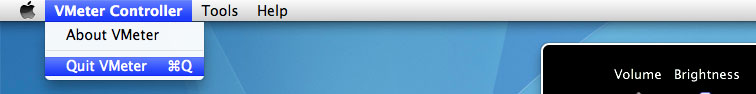
Exit: Click the V, and then on the VMeter Controller drop down menu in the upper left (not in the control panel, but on the status bar). Choose “Quit VMeter” from the drop-down menu.
Upside Down Mode: If you’d like to orient the VMeter so that the USB cable is towards the top, you can select “Upside down” to have it draw the lights from the opposite end.
Recalibration: If the touch strip is behaving unexpectedly, you can recalibrate it by unplugging and replugging, or by selecting “Tools” in the upper left menu, and then “Recalibrate.” This normally shouldn’t be necessary as the VMeter is constantly adjusting to changes in its environment, but may be required in rare cases.
VMeter USB HID Protocol:
This information can be used to use the VMeter with your own software or hardware, even a host shield for arduino.
The VMeter continously sends packets of 16 bytes and receives packets of 8 bytes about every 4ms (subject to change).
Some of the bytes sent from the VMeter are diagnostic and may change.
8 BYTE PACKET SENT TO VMETER:
packet[0]: always required, not actually sent to VMeter but must be 0.
packet[1]: command (see below)
packet[2]: command parameter
packet[3]: brightness: 0-16, 0 is off, 16 is max brightness
packet[4]: binary value of lights 0-7 (when packet[1] == 2)
packet[5]: binary value of lights 8-15 (when packet[1] == 2)
packet[6]: binrary value of lights 16-23 (when packet[1] == 2)
packet[7]: binrary value of lights 24-31 (when packet[1] == 2)
packet[8]: binrary value of lights 32-38 (38 lights in total) (when packet[1] == 2)
commands:
- 1: When packet[1]==1, packet[2] contains the column height, 0 thru 38. If upside-down mode is on, it draws from the top
- 2: When packet[1]==2, packet[4-8] contain the binary value for each group of 8 lights. For instance, sending a 6 in packet[4] would turn on the 2nd and 3rd lights since 6 == 0b00000110
- 251: When packet[1]==251, packet[2] sets the ignoreTouch mode. If 1, touches don't change the lights. If 0, touches override whatever is currently controlling the lights (MIDI for instance).
- 252: packet[2] turns on / off upside-down mode.
- 253: recalibrate. Sometimes this might be necessary if you move the VMeter.
- 254: Prepare to update firmware. Puts the VMEter in a special state that will accept new firmware. Requires additional software and firmware
16 BYTE PACKET RECEIVED FROM VMETER:
packet[0]: Touch state, 0 for off, 1 for on
packet[1]: not used
packet[2]: current light position being displayed, 0 - 38
packet[3]: cap sensor 1 value, closest to VMeter label and USB port, can be negative
packet[4]: cap sensor 2 value, can be negative
packet[5]: cap sensor 3 value, can be negative
packet[6]: cap sensor 4 value, can be negative
packet[7]: cap sensor 5 value, can be negative
packet[8]: cap sensor 6 value, can be negative
packet[9]: cap sensor 7 value, can be negative
packet[10]: cap sensor 8 value, can be negative
packet[11]: diagnostic, not specified
packet[12]: touch_pos (0-255)
packet[13]: pressure, or a sum of all the cap sensor differentials (current value - ref value). Can be negative?
packet[14]: not used
packet[15]: not used
OLDER VERSIONS:
OS X:
0.91 -> 0.92: Fixed unplug error, overall stability. Added icons.
Original Volume Control Only (no MIDI):
Instructions:
Install and run the software, plug in the VMeter to a USB port, and you’re good to go!
Note: On Windows, the first time you plug in the VMeter, Windows will do a special configuration, and you may need to unplug and re-plug the VMeter after its done.
Touching the VMeter should now change your computer’s volume.
In Windows, the software sits in the system tray (bottom right). Right click the V icon to change the brightness and to get more help. Once the settings page is displayed, it will say “Please connect VMeter” if it isn’t connected already. If you experience any problems, first try unplugging and replugging the VMeter.
On OS X, the V icon is in the upper right next to the time. Click it to change brightness and get additional help.
Usage Tip: The VMeter works best when it’s permanently installed somewhere. You may notice some erratic behavior if you’re holding it in your hand as it can sometimes detect motion to the side and behind it. It will automatically recalibrate as soon as you install it.
We’re still in beta mode, so let us know if anything doesn’t work just right and we’ll get right on it.
thanks!